Even experienced craftsmen are far from always able to ensure the natural movement of the coolant along the heating circuit. It so happens that water moves through the system, but there is not enough heat in the house.
Increasingly, owners of private houses prefer to install heating systems with pump circulation, which are quite diverse and convenient. In this article, we examined the basic schemes for organizing heating with coercion, supplementing the material with visual illustrations and photos.
We also selected useful videos with the recommendations of specialists in installing pumping equipment for the heating system. This will allow you to understand in detail the issue of installing the pump.
The principle of the system with coercion
The circulation pump is a small electric device that is designed extremely simply. An impeller is located inside the casing, it rotates and gives the necessary heat-transfer agent circulating through the system. The electric motor that provides rotation consumes very little electricity, only 60-100 watts.
The presence of such a device in the system greatly simplifies its design and installation. Forced circulation of the coolant allows the use of small diameter heating pipes, expands the possibilities when choosing a heating boiler and radiators.
Image Gallery
Photo from
In heating systems with forced circulation, there are no shortcomings of heating circuits with gravitational motion of the coolant. They easily cope with the maintenance of large areas, multi-storey buildings, systems with several circuits
Since in coolant circuits with pump circulation the heat carrier moves much faster, it requires adjustment, control, balanced distribution
Forced-type heating systems are generally arranged in a closed circuit so that volatile devices do not work in vain. In such schemes, a special expansion tank is required that does not communicate with air
The use of a pump that stimulates the movement of heated water to heating devices is necessary if one boiler is used to supply coolant to two or more heating circuits
A forced heating system is necessary when constructing circuits with a lower wiring. Due to the design features, the natural movement of the heated coolant to the devices and back to the boiler in such systems is difficult
Heating with pumping of the heat carrier is volatile. In addition, his scheme uses expensive devices that are not needed for natural circulation
By installing control devices and stimulating the movement of the coolant in the circuit, the gravity system can be converted into a pumping system. However, this will not make sense without changing pipes, which in natural schemes are much larger in diameter
Thanks to the use of a circulation pump, the diameter of the pipe used in the assembly of the supply and return lines is significantly reduced. But due to the need to install valves, safety and control devices, the total cost is much higher than that of gravity options
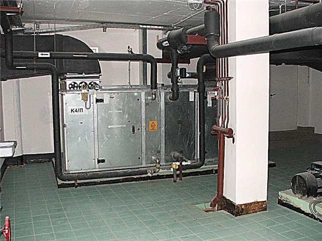
Fragment of heating with forced circulation
Valves for pump heating
Expanzomat - tank for expanding coolant
A complex of several heating circuits
Bottom heating system
Circulation pumps in heating systems
Converting natural heating to artificial
Pipes in pump-type heating systems
Very often, a system that was originally created with the expectation of natural circulation works unsatisfactorily due to the low velocity of the coolant through the pipes, i.e. low circulation pressure. In this case, installing a pump will help solve the problem.
However, one should not get too carried away by the speed of the water in the pipes, since it should not be excessively high. Otherwise, over time, the design may simply not withstand the additional pressure for which it is not designed.

If an open expansion tank can be used in systems with natural coolant circulation, then in closed circuits, preference should be given to a closed sealed container
For residential premises, the following limit norms for the velocity of the coolant are recommended:
- with a nominal pipe passage of 10 mm - up to 1.5 m / s;
- with a conditional pipe passage of 15 mm - up to 1.2 m / s;
- with a conditional pipe passage of 20 mm or more - up to 1.0 m / s;
- for utility rooms of residential buildings - up to 1.5 m / s;
- for auxiliary buildings - up to 2.0 m / s.
In systems with natural circulation, the expansion tank is usually placed in the feed. But if the design will be supplemented by a circulation pump, it is usually recommended to move the drive to the return.

The circulation pump device is very simple, the task of this device is to give the coolant an acceleration sufficient to overcome the hydrostatic resistance of the system
In addition, instead of an open tank, you should put a closed one. Only in a small apartment, where the heating system has a small length and a simple device, you can do without such a rearrangement and use the old expansion tank.
Calculations for forced heating systems
A properly organized system with forced circulation requires complex engineering calculations. But some formulas allow you to evaluate the state of the system and create a more accurate idea of the necessary alterations, especially when it comes to a small house or apartment. The power of heating equipment is usually selected based on the size of the premises that are supposed to be heated.
Image Gallery
Photo from
The energy consumption of a circulation pump designed for use in domestic autonomous heating circuits typically ranges from 60 to 100 watts. They spend no more than an incandescent bulb
In systems with primary and secondary circuits connected to them, in the complex of low- and medium-temperature heating systems, a group of pumps is used. All independent and dependent rings are equipped with devices
There is a rule according to which even in simple heating circuits with forced circulation, one pump is supplemented with a duplicate installed on the bypass. It is needed in case of failure of the main unit
The power of the circulation pump should allow the coolant to freely overcome the resistance in the pipeline. The speed of movement, which the pump must provide, is taken according to the tables with typical parameters. For example, through pipes Ø 10.15.20 mm, water should move at a speed of 1.5; 1,2; 1,0 m / s
Low power device
Heating Circulation Pump Group
Spare device in case of breakage
Circulation pump installation option
Typically, manufacturers recommend: that the flow rate recorded in liters per minute correspond to the number of kilowatts of boiler power. This means that for a 40 W boiler, a coolant flow rate of 40 l / min will be most suitable.
In the same way, the water consumption for a single room or group of rooms is calculated. In this case, they are guided by the total power of the radiators installed on the site.

The rate of movement of the coolant along the heating system circuit largely depends on how correctly the diameter of the pipes is selected
The diameter of the heating pipes is determined in accordance with the set flow rate of the coolant:
- at a flow rate of 5.7 l / min, half-inch pipes are required;
- at a flow rate of 15 l / min, pipes are needed for three quarters of an inch;
- at a flow rate of 30 l / min inch pipes are needed;
- at a flow rate of 53 l / min, pipes per inch and a quarter are needed;
- at a flow rate of 83 l / min, one and a half inch pipes are required;
- at a flow rate of 170 l / min, two-inch pipes are required;
- at a flow rate of 320 l / min, two and a half inch pipes, etc. are needed.
To determine the parameters of a suitable circulation pump, it is necessary to measure the length of the entire heating circuit to which it will be connected. For ten meters of the system, a pump head of 0.6 m is needed. Using simple calculations, we get that for a system 60 meters long, a 3.6 m pump is needed.
However, these parameters are only valid for a system in which the diameter of the pipes is correctly selected, as indicated above. If too narrow communications are used, it will be necessary to take a more powerful pump in order to overcome the excess hydraulic pressure that arises in the system due to incorrect pipe selection.
Detailed recommendations for choosing a circulation pump are given in this article.

An automatic air vent or mechanical device to remove excess air from the Majewski crane is needed to remove air from a closed system. These devices are necessary in heating circuits, they help prevent the problem of airing. Such devices are installed on radiators, on supply risers, as well as in problem areas of complex heating circuits
This rule also works in the opposite direction: if the pipes are wider than necessary by the standard, the rated capacity of the circulation pump should be reduced.
An important component of forced heating systems is the security group:
Image Gallery
Photo from
As part of the safety group, mounted on closed heating circuits without fail, three devices that provide trouble-free operation, protect equipment from wear
The security group includes an automatic air vent used to discharge air plugs, a pressure gauge and a safety valve that dumps excess coolant when it expands from heating
Security group devices are most often located in a monolithic bronze case. However, you can purchase and install them separately, but so that the safety valve is after the boiler
For reliability of obtaining pressure data in a closed system, the pressure gauge is placed either next to the safety valve, or with a recharge valve, replenishing the coolant in the event of a pressure drop
An automatic air vent, without the participation of the system owners, opens slightly and releases air released from the water circulating along the water circuit during heating and collecting in large bubbles
The safety valve, in case of an increase in pressure in the system that occurs during heating of the coolant, opens slightly and releases water that creates excess pressure
Spring valves for powerful and branched heating systems are equipped with a tube through which coolant is discharged so as not to burn those present
It is recommended that water or antifreeze solution discharged by a safety valve be passed through a funnel so that the condition of the pipeline can be monitored at the initial stages
Installation of a heating system security group
Devices for safe operation of heating
Rules for installing security devices
Pressure gauge with make-up valve
Automatic air vent with pressure gauge
Pressure relief valve group with pressure gauge
Spring drain valve
Sludge overgrown heating pipes
Experts recommend purchasing not one, but two such devices at once. One is the main, and the second is in reserve. It can be installed on the bypass or stored in the pantry.
The circulation pump is usually resistant to breakdowns, but sensitive to the quality of the water in the heating circuit. To extend the operation of heating equipment, it makes sense to provide for filtering the coolant and timely flushing of the system.
Circuit diagrams of pump circulation systems
Forced circulation heating systems are distinguished as follows:
- as one or two-pipe (option for connecting pipes to radiators);
- with vertical risers or horizontal highways;
- dead ends or with the passing movement of the heat carrier
- with top or bottom wiring.
Monotube systems are becoming less common, since their disadvantages far exceed the advantages. This is a very simple option, in which the radiators are connected in series. The coolant passes through each heater one by one, gradually cooling.
Obviously, with such a scheme, the first radiators will heat the room better than those located at the end of the system. It is necessary to install more radiators on the final section of the highway than at the beginning in order to smooth out the temperature difference.

One-pipe heating systems are easy to implement and cost inexpensive, but the problem of uneven heating and the dependence on the breakdown of one radiator made them practically unclaimed in modern conditions
Such a device is extremely inconvenient, since it is impossible to turn off only one radiator in the event of a breakdown, you will have to drain the coolant from the entire circuit. The two-pipe scheme involves connecting each radiator in parallel using two pipes to a common trunk.
Of course, for this you will have to use more materials, the total cost and time for installation will be higher than when using the single-tube version.

Two-pipe heating systems make it possible to evenly heat each room, while a breakdown of one radiator will not cause a shutdown of the entire circuit
On each radiator with two-pipe connection, shut-off valves are installed. This makes it possible, if necessary, to remove or turn off only one radiator, while the remaining elements of the system continue to function in normal mode.
Warming up with this scheme is carried out evenly, since the coolant enters each radiator in a separate line, and then returns to the boiler for heating, and does not move along the other radiators.
Vertical risers are used in multi-storey buildings; it is convenient to connect radiators located on different floors to them. The vertical design contributes to the rapid removal of air entering the system, which significantly reduces the likelihood of air congestion.

Creating a vertical heating system will cost a lot, but this is an effective air-resistant design, it is perfect for installation in multi-story buildings
In horizontal schemes, the main highway, to which radiators are connected in parallel, is located, as the name implies, in a horizontal plane. This type of system is suitable for heating one-story buildings of a large area.
A relatively inexpensive option is not immune to the formation of air jams. To prevent problems of this kind, automatic air vents are used. The rules for removing the air plug from the heating system are discussed in detail here.

Horizontal heating systems are relatively inexpensive, they are usually used in the design of large buildings on one or two floors
Uneven heating is characteristic not only for single-pipe systems, but also for a dead-end version of heating, which is quite widespread.
In such a scheme, the flow of coolant is carried out in the direction opposite to the movement of the return.As a result, radiators appear in the system, receiving a somewhat cooled coolant, which after them enters the return pipe.

In dead-end systems, radiators that are remote from the riser receive less heat than those located near it. In associated circuits, all elements of the system operate in an equivalent mode
As a result, more heat comes to the first radiators from the riser, and less to the remote ones. In small areas this moment may not be so noticeable, but in spacious houses it will be noticeable. In this situation, it is recommended to make several highways smaller than one long, so that the entire coolant circulates along the branches with approximately the same temperature.
A passing scheme is based on the same length of circulation rings throughout the house, which allows for extremely accurate uniformity of heating. But to implement this option of wiring is not easy, because you need to hold a large number of pipes.

The upper wiring in heating systems is used in the presence of an attic, on which an expansion tank can be installed. If this is not possible, you can successfully implement the lower heating wiring
The upper and lower wiring were named at the location of the supply pipe. In the first case, the coolant enters the system from above, and in the second from below.
At the top wiring, the expansion tank is installed at the highest point in the system, the coolant is distributed through the system under the influence of gravitational forces. The return here will be below the radiators. To implement such a project in a private house, an attic is needed, on which a tank is installed.
If there are no conditions for the upper wiring, use the second option, when the coolant is supplied from below, and the return is installed above the radiators. The task of moving the coolant with a sufficiently high speed lies mainly with the circulation pump.
Such a scheme is mounted gradually, from the lower floor to the upper, while the supply line is made with a slight slope to prevent the occurrence of air jams.
To remove air jams, heating utilities are equipped with automatic air vents:
Image Gallery
Photo from
Automatic collector heating air vent
The device for air removal from a heat-insulated floor
Air separator in the heating system
Location of air vent
Where to put the circulation pump?
Most often, the circulation pump is installed on the return, and not on the supply. It is believed that there is a lower risk of rapid wear and damage to the device, since the coolant has already cooled down. But for modern pumps this is not necessary, since bearings with so-called water lubrication are installed there. They are already designed specifically for such operating conditions.
This means that it is possible to install a circulation pump at the feed, especially since here the hydrostatic pressure of the system is lower. The installation location of the device conditionally divides the system into two parts: the discharge area and the suction area. The pump installed on the supply, immediately after the expansion tank, it will pump water from the reservoir and pump into the system.

The circulation pump in the heating system divides the circuit into two parts: the discharge region, into which the coolant enters, and the vacuum region, from which it is pumped out
If the pump is installed on the return line in front of the expansion tank, it will pump water into the tank, pumping it out of the system. Understanding this point will help to take into account the features of hydraulic pressure at various points in the system. When the pump is running, the dynamic pressure in the system with a constant amount of coolant remains constant.
It is important not only to choose the best place for the installation of pumping equipment, but also to install it correctly. We recommend that you familiarize yourself with the nuances of installing a circulation pump.
The expansion tank creates the so-called static pressure. Relative to this indicator, an increased hydraulic pressure is created in the discharge area of the heating system, and a lower pressure is created in the rarefaction region.
Image Gallery
Photo from
Installation of a heating expansion tank
Location of the pump relative to the tank
Expander in a wall-mounted boiler system
The volume of the expansion tank in the heating system
The vacuum can be so strong that it reaches atmospheric pressure or even lower, and this creates conditions for air to enter the system from the surrounding space.
In the area of increasing pressure, air, on the contrary, can be pushed out of the system; sometimes, boiling of the coolant is observed. All this can lead to incorrect operation of heating equipment. To avoid such problems, overpressure in the suction area should be ensured.
To do this, you can use one of the following solutions:
- raise the expansion tank to a height of at least 80 cm from the level of the heating pipes;
- place the drive at the highest point in the system;
- disconnect the drive pipe from the feed and transfer it to the return line after the pump;
- install the pump not on the return, but on the flow.
It is far from always possible to raise the expansion tank to a sufficient height. Usually they put it in the attic, if there is the necessary space. At the same time, it is important to adhere to the rules for mounting the drive in order to ensure its smooth operation.
Detailed recommendations on the installation and connection of the expansion tank we have given in our other article.
If the attic is not heated, the drive will have to be insulated. It is quite difficult to rearrange the tank to the highest point in the forced circulation system if it was previously created as natural.
We will have to redo part of the pipeline so that the pipe slope is directed to the boiler. In natural systems, bias is usually made to the boiler.

The expansion tank installed in the room does not need additional protection, but if it is installed in an unheated attic, you should take care of the thermal insulation of this device
It is usually not difficult to change the position of the tank nozzle from the feed to the return. And it is just as simple to implement the last option: embed the circulation pump on the supply line behind the expansion tank into the system.
In such a situation, it is recommended to choose the most reliable pump model, which for a long time will be able to transfer contact with hot coolant.
More detailed information on the calculations required when choosing a circulation pump is contained here:
In this video, the device and the installation procedure of the circulation pump are described in detail:
Forced heating systems are not as complex as they might seem at first glance. But in order to realize such a task, it is necessary to correctly perform the calculations and draw up a competent project. Under these conditions, you can provide your home with reliable and efficient heating.
Are you choosing the optimal scheme for arranging a forced-heating heating system in your home? Maybe you have questions that we did not consider in this article? Ask them to our expert in the comment block.
Or do you want to supplement the material with practical tips for installing pumping equipment? Write to us - your comments will help many newcomers.